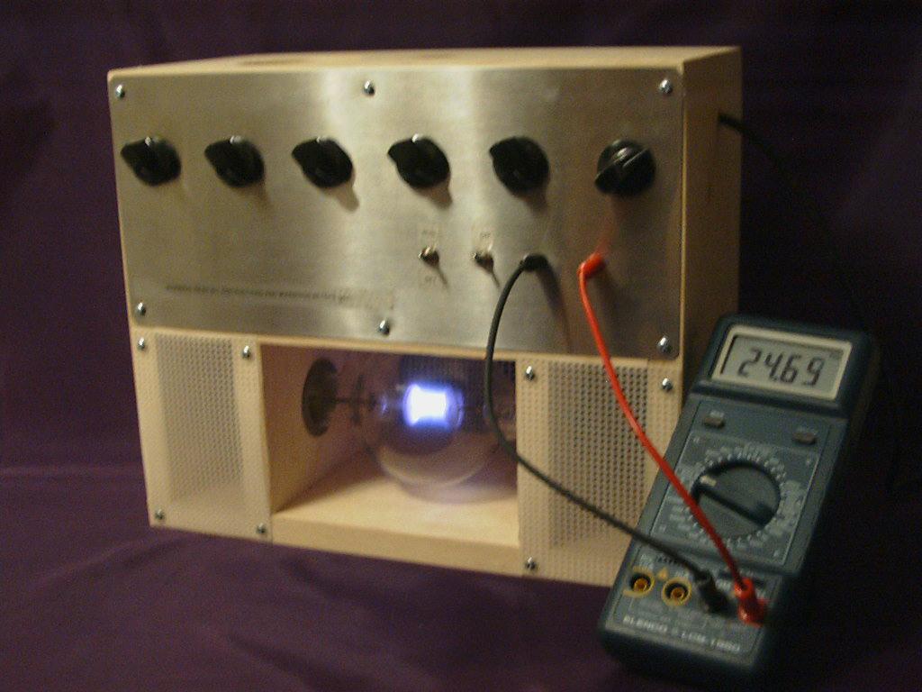
EMEM2 and EMEM3 Construction Notes 7-28-99

EMEM3D with LCM-1950 Meter
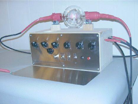
EMEM3DV or EM7V with Ground Plate (They look the same.)
The EMEM2 was invented by Dan Tracy. In a conversation with "Doug", the inventor of the large coil device, he commented that the EMEM2 does kill Lyme disease and that it is a lot of machine for the money. It has also been demonstrated to be useful for many other conditions. This version uses 6 pots to give a frequency range of about 7Hz to 10KHz and finer tuning in the important 2,000Hz range. Bruce Stenulson's ideas of having a set/run switch and having adjustable ballast resistors are incorporated. The adjustable ballast is handier than my old clip lead method! For simplicity of construction and economy I have put the resistors in series instead of using a separate one for each power setting. Instructions for a contact/radiant version and then modifications for a pure radiant EMEM3 version are given.
Warning: Very high voltages are involved. If you are not familiar with the safety procedures required, please do not try any of this. Also, in view of the current lawsuit lunacy, it needs to be pointed out that this device has not been approved for use on humans. It probably should not be used near those with heart pacers or irregular heart rate. It is a research device only that you use at your own risk.
The frame or box consists of 3 shelves which are pieces of 1X6 lumber. The top and bottom shelves are 2" longer than the tube, and the middle shelf is 1/2" longer than the tube, allowing 1/4" space on each end of the tube. These shelves are held together by 2 1X6 upright end pieces that are 10" long. So the whole thing looks like a small 3 shelf book case. The size of the power supply and the length of the tube determine the size of the box needed to house the unit. There is a 4-3/4" space between the top and middle shelves, and a 4-1/2" space between the middle and bottom shelves.
Between the bottom and middle shelf is a 4-1/2" space where the tube goes. The tube has usually been in the bottom area for reasons of comfort if one wants to rest their arms on a table and wrap fingers around the tube. It could just as easily be put in the top area if desired, though the frequency may be easier to set if the pots are on top and the tube below. The tube is supported by three 4-1/2 inch long upright 1X6 supports which go between the shelves. One is in the center, and one is 2" from left end - that is, there is a 2" space between the support and the end piece. The right support can be 2-3" from the right end piece to leave room for ballast resistors. The supports also serve to keep fingers away from high voltage at the ends of the tube. 1-1/2" holes for the tube are drilled though the 3 tube supports. The holes are centered up and down, and the hole centers are 2" from the front. There is room for foam padding around the tube at each hole.
The middle shelf has the ignition coil, the Darlington 2N6059 transistor, the 555 timer board, and the power supply. The coil is mounted in the back left corner with the "business end" facing left. The tip of the spark plug is about 1/4" or so from the end support. A hole is drilled in the middle shelf below the end of the coil for the wire from the spark plug to the tube. In front of the coil on the far left (1-1/4" or so from the upright) is the transistor and its 2-1/4 by 2-1/2 by 1-1/2 inch thick heat sink. A smaller heat sink can be used with this version if desired as the transistor stays cooler than with previous models. The heat sink lays on its side with the contacts on the right. It can be held in place by a strap consisting of a heavy solid copper wire and 2 wood screws. The 2 inch square 555 timer board is mounted on 1/4" spacers to the right of the heat sink. It may be desirable to move the 555 board as far as convenient to the right to keep it farther from the spark gap. Above the transistor, under the top shelf is a 12 volt 3" muffin fan. The fan is mounted on 3/4" spacers to space it away from the top shelf. The plugs cut out of the tube supports can be used as spacers if desired. The power supply should put out between 12 and 18 volts DC and at 5 amps or more. It takes up the right part of the middle shelf. On the far right of the middle shelf a hole is drilled for the wire to the ground end of the tube and ballast resistor assembly.
At the left end of the top of the unit in front of the coil/transistor/555 board/fan area is a 6" by 13-1/2" piece of sheet metal or plexiglass that holds the six linear pots. This is attached to the top and middle shelves and keeps fingers away from the coil, etc. Holes for the pots can be about 2" from the top of the sheet metal and evenly spaced along the length of the sheet. I have mine set in 1-1/8" from each end and then evenly spaced at 2-1/4" apart.
On the same plate, 2" from the bottom of the plate starting 1- 1/4" from the right side are the on-off switch, set-run switch, and the tip jacks for the frequency counter.
The entire back of the unit is covered with heavy plastic screen usually used for needlepoint. It is called 7 Mesh Quick Count and is sold by Walmart in their arts and crafts section. The area to the right of the plate that holds the pots is covered. The 2" area at the left end of the tube is covered. The opening at the right end of the tube is covered with a piece of plexiglass that measures 4-1/4" by 5-3/4" which holds the jacks for the ballast resistors. So all openings are covered except where access to the middle area of the tube is needed.
For the basic schematic of the device, see http://www.royalrife.com/emem2.jpg
Wrap a couple turns of #20 bare solid copper wire around the end of a Champion CJ-6 spark plug where the spark plug wire normally would attach. The wire causes the plug to fit snugly into the metal contact in the end of the coil. The plug is inserted into the coil and is taped to the end of the coil with electrical tape (do not cover the threads). The coil is a standard 12 volt NAPA external resistor automotive coil part number IC12SB. Around the threads on the plug wrap #16 or larger stranded copper wire and twist the ends until it is snug. The ends can be soldered to keep the wire in place. This wire goes to the "hot" (left) end of the tube. This connection can also be soldered but extra flux may be needed. The plug gap is around 0.010 inches. I use the largest gap that will still produce 10KHz.
To identify the pins on the Darlington 2N6059 transistor, turn it upside down, pins facing up. Rotate it so that the pins are nearer the left side. "E" is farthest from you, and "B" is nearest you. "C" is the case. The transistor is connected as follows: "C" goes to the negative post on the coil. "E" goes to the negative post on the power supply/common ground, as does the negative on the 555 board. "B" goes to the output of the 555 timer board or to the set/run switch.
Bruce's set/run feature is handy as you can easily try out new frequencies as they are discovered. For that feature, mount a black and a red tip jack that fit your frequency counter probe and a SPDT switch on the pot plate in front of the 555 timer board below the pots. The black jack is connected to the 555 timer board ground/system common ground. The output of the 555 board goes to the center contact of the switch. The top switch contact goes to the red jack and the bottom one to "B" on the Darlington. You can label the bottom switch position "SET" and the top one "RUN". I also mark frequencies on the plate to make the unit easier and faster to use and for those who do not want to buy a meter. I normally just use those markings myself when I use the device.
The tube is the same as the leaded glass tubes often used in Rife/Bare units. Lengths of 16" to 5' (yes, five feet) have been used, and all work fine. 18" is most commonly used. The tube does not run as bright as with a Bare unit, by the way. The left electrode is attached to the wire from the threads on the spark plug. The other electrode is attached to the common ground (the earth-ground on the wall socket, the power supply negative and the connection for the foot plate) through a ballast resistor or resistor assembly.
Tech America has 25 watt resistors that work well as ballast resistors. Dan emphasizes that they should be at least 20 watts as it can be a shocking experience when one of them fails. It can be anywhere from 10K to 60K or even much larger. Many of the units currently being produced have a fixed 10K ballast. This produces adequate results. The larger the resistor, the higher the voltage at the copper wrap as measured to the foot plate. If the "cold" end of the tube is not connected to ground at all, the output of the EMEM2 (voltage from copper wrap to foot plate) is greatly increased. So if you want something similar to the Australian fling-yourself-against-an-electric-fence therapy, you can disconnect the cold end of the tube altogether. This is not recommended and no one has, to my knowledge, done this twice. It is, however, what happens if a ballast resistor fails. I have had a couple (none from Tech America) fail so far.
Tip jacks or banana jacks for the ballast resistors can be mounted on a 4-1/4" by 5-3/4 piece of plexiglass that covers the opening at the right end of the tube. The first jack is connected to the wire at the right end of the tube and can be marked "common" even though it is not connected to the common ground. A second one (at least one inch away) is connected to the common ground. A (well insulated) jumper with tip plugs or banana plugs between these two jacks would give zero ohms ballast. This position would give you the lowest voltage between the copper wrap and the foot plate. It also causes the highest current flow through the tube itself and the brightest tube. Dan Tracy reports that this setting gives the highest radiant output as measured in terms of die-off reactions with Lyme disease sufferers who just sit in front of the device without touching the tube or foot plate. So this second jack can be marked 0/Radiant.
What follows is just one possible configuration. Other combinations can be used as desired. From the second jack, run a 25 watt 40K to a third jack marked 40K. From the third jack, run a 40K to a fourth one marked 80K. From that one, run a 100K to a fifth jack marked 180K. From that one, run a 100K to a sixth jack marked 280K. The higher the value, the higher the voltage from the copper wrap to foot plate. WARNING: The EMEM2 must be turned off before the jumper is moved. As a safety feature, one also may run a wire from the common jack/tube end to the sixth jack. Then if someone unplugs the jumper without turning the machine off the result is not as dramatic.
The foot plate needs to be large enough to accommodate most of both feet - 6" by 8" or so and is connected to the common ground.
Around the left or "hot" end of the tube go 6 or 7 turns of 1/2" copper strap (thin sheet copper), with about 1/8" or so between the turns. This goes just to the right of the left tube support, not touching the electrode. It is secured to the tube with a layer of electrical tape at each end. To this is attached a wire that goes to the small contact. For the small contact plate, I am using a piece of stainless that is 3-1/2 by 4". Most any size will do. The small contact is being used all over the body including on closed eyes.
If you choose to make your own power supply, a 12 volt 4 or 5 amp transformer (6-0-6) can be used. Dan is currently using one rated at 4 amps from Marlin Jones. They also have one that is 12-0-12 and 10 amps. Just half of the output of that one is used. A full wave bridge rectifier assembly rated at 25 or so amps and 25-50 volts is used to turn the transformer output into pulsed DC. The AC contacts on the rectifier are diagonal from each other, by the way. A capacitor rated at 50 volts and 4700uf goes across the rectifier output. Be sure to attach the positive wire on the capacitor to the positive output of the rectifier, by the way. If desired, two or more capacitors can be used in parallel. (Hook all the + wires to the + side and all the - wires to -.) Jim Bare recently reported adding over 20,000uf to the power supply of a Stenulson unit. He reported that the output of the unit increased and that a lower output setting had to be used. Put a 3 amp fuse and switch in either side of the transformer primary. (A 3 amp fuse in the primary is adequate even if 10 amps from the secondary is desired.)
The frequency source must put out half-wave/positive DC pulse. We have been making these in the form of a standard 555 timer circuit that has 0.1uf capacitors at pins 5 and 2/6 to ground. If possible, a fairly accurate capacitor should be used at pin 2/6. From pin 6 to pin 7 is a 600 ohm resistor (use a 1K trimmer) in series with a 1M, a 10K a 5K pot, and a 1K pot. The 1M is pot #1, the 10K is #2, the 5K is #4, and the 1K is #5. Between pins 7 and 8 there is a 190 to 200 ohm resistor (a trimmer can be used, I use a 200 ohm 1%) in series with a 10K and a 5K pot. The 10K is pot #3, and the 5K is #6. The pots are wired so that when they are full counter-clockwise, the resistance is maximum. (Reducing the resistance raises the frequency.) Pin 1 is grounded. Pins 4 and 8 go to the 12 volts positive. There is also 1.2K resistor in the output (pin 3) to reduce the voltage to 1.6-1.7. All resistors are 1/2 watt.
For a schematic of the 6 pot 555 circuit see http://www.royalrife.com/555.jpg
If a meter is not used to set frequencies, a frequency counter must be used to calibrate the unit - just mark the desired frequencies on the plate that the pots mount on. (First make sure that the unit will produce 10,000Hz before you begin.) Start with all pots in the full counter-clockwise position. The left pot must be all the way clockwise before you start turning up the second pot, and so on. Disconnect the coil (or select "set" if you have this feature) before you do this or most frequency counters will be overpowered by all the harmonics. The counter is connected to the common ground and the output from the 555 board. If you cannot get the top end to go up to 10KHz, the actual value of the 0.1uf at pin 2/6 may be above 0.1. If that capacitor is accurate, you can adjust the top end to 10KHz with the trimmer from pin 6 to pin 7. So if you have a good capacitor a pin 6, just adjust the trimmer pot from pin 6 to pin 7 to give you 10KHz at the top.
To use the device, one can place the fingers around the tube (left hand at the copper ribbon) and then place the feet on the foot plate. Or, the small plate can be applied as desired. A layer of damp paper towel with a dash of salt is often used on the small plate. If you touch the ribbon or small plate lightly, you will get a small shock. This does not happen if firm pressure is immediately applied. It works best (no shock) if you grasp the tube or apply the small plate and put the feet on the foot plate before turning the unit on or selecting
How can you tell the device is working and not just making light and the audible frequency? On a unit that the inventor built, I selected 432Hz, grasped the copper wrap and put my bare feet on the foot plate. Then I slid my hand off until just the finger tips were in contact. Then I removed the fingers one by one until just one finger tip remained. The voltage/current was high enough to be uncomfortable. With larger ballast resistors from the ground end of the tube to ground, it can be quite painful with only one finger tip on the copper. The voltage at the copper wrap increases with the frequency according to an analog meter that I have. These readings are not considered reliable. As with pad devices, less can be felt at higher frequencies so more voltage can be tolerated if desired. With the EMEM2, one may want to use a higher value ballast at high frequencies of around 5KHz and above. We do not know for sure, however, that more is always better. Research by Dr. Gary Gear (E.E.) suggests that this may not be the case.
To use the EMEM2 as a non-contact radiant type of device, select 0 ohms as a ballast. Sit three feet or so from the tube. With a standard leaded glass tube, fairly long runs can be tolerated in the radiant mode. Use of the ground plate may be used.
The EMEM3 is a straight radiant device that uses a Cheb high pressure phanotron tube. It has been reported by the inventor and many others to be very effective. No copper wrap is used. Only 2 tube supports are used, placed toward the ends of the tube near the end caps. Tube holes are 1-3/4". Best results are reported by the inventor with no ballast resistor - just connect the right end of the tube to the common ground. By best results, I mean maximum die-off and health improvement as reported by users. The 4-1/2" space is plenty for the phanotron bubble, and it can be centered up and down and front to back in the supports. The middle board can be as short as 12". That makes the top and bottom boards 13-1/2", just right to take the 13-1/2" face plate.
No ground plate is used. There is plenty of power radiated so that it is not needed. Short run times are suggested at first - only 2 minutes for Lyme disease. People are sitting anywhere from 1 foot to 10 feet or more from the unit. The device works well for treating a group, and even those seated behind the unit report good results.
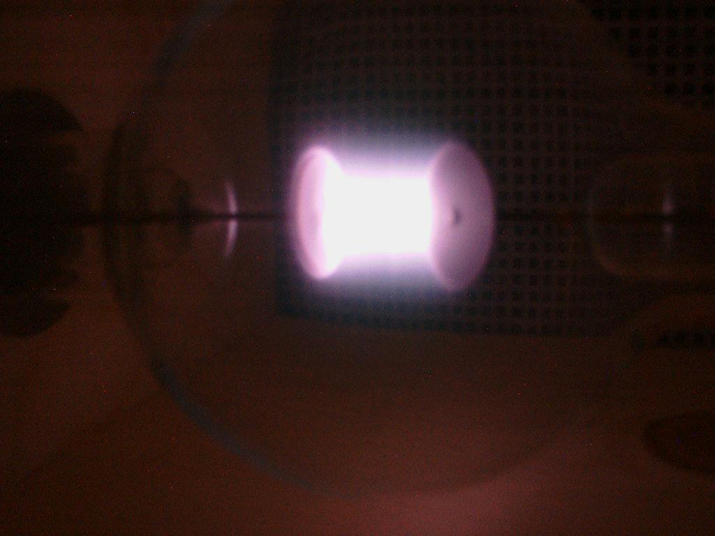
75 mm Pressure Helium Phanotron tube
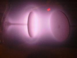
15mm Pressure Helium Phanotron tube
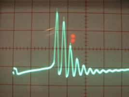
Damped wave scope picture from EMEM3 with spark, probe in front of tube
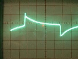
No spark scope picture from EMEM3, probe in front of tube