This version of the EMEM3D leaves out the internal 555 timer circuit, the 6 associated potentiometers, the internal/external switch, the set/run switch, the frequency counter instrument, and the pin jacks to plug in the frequency counter.
Instead, it uses a programmable frequency source such at the F150. This is much more practical, allowing dozens or hundreds of frequencies and durations to be easily programmed and used with little effort or attention.
The elimination of the above parts also greatly simplifies construction. The overall cost is raised by only about $100 compared to the standard EMEM3D, but the instrument becomes much more usable.
The Phanotron tube may also be used as a contact device. Just disconnect the ground end and cap that wire with plastic tubing. Add a grounding contact pad that may be plugged into the ground jack. Also illustrated is the optional extra, a Violet Ray bulb to be used as a contact device in place of the Phanotron tube.
CAUTION: Using either the Phanotron or the Violet Ray bulb as contact devices with a grounding pad may theoretically increase effectiveness by bringing the frequencies into direct contact with particular areas of the body, but there is also a risk of very unpleasant, high-voltage shock. VERY IMPORTANT precautions are ESSENTIAL to avoid this. First, the Phanotron and/or Violet Ray bulb must be mounted and insulated in such a way that the person handling the bulb will not inadvertantly be shocked by accidentally touching any contact points. Secondly, the following sequence should be followed to avoid shocks.
When dis-engaging, the reverse sequence should be used to avoid shocks. In other words, turn up the potentiometer resistance to maximum and shut the unit off before removing the bulb from skin contact.
Note: Study the drawing here before ordering parts. In many cases, 2 or more of the parts listed are needed.
Click on pictures below for an enlarged view.
![]()
Parts illustrated in drawing
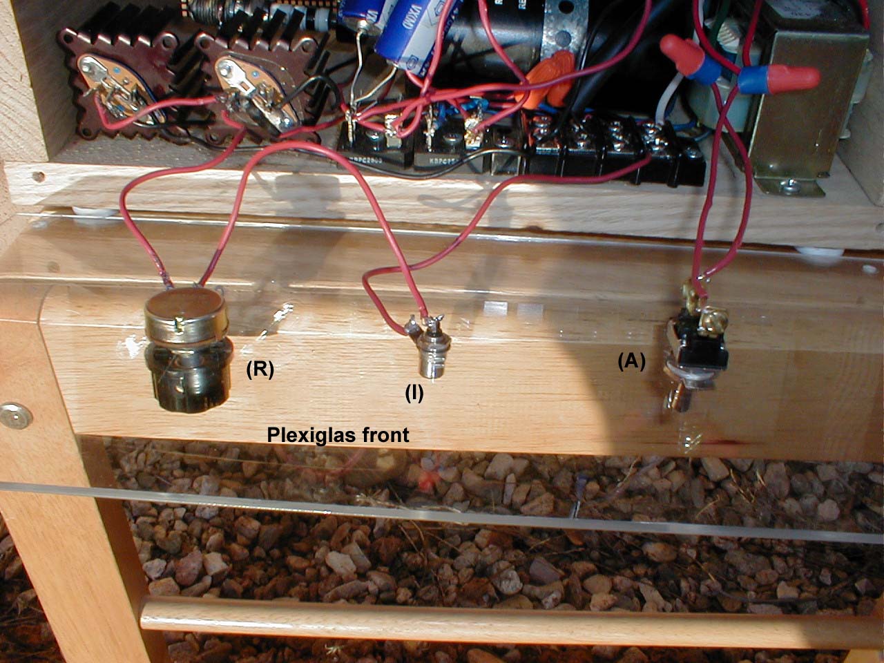
(A) 110 V On/Off Switch (hardware store or Radio Shack)
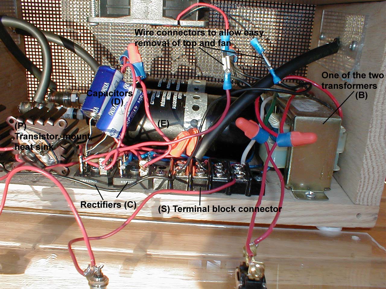
(B) 120 V to 12 V Transformers -- Marlin P. Jones (800-652-6733)
has the 4 amp 12 volt (6-0-6) stock number 7840-TR. They also
stock the 10 amp
12-0-12 stock number 7846-TR. The 10 amp model is much larger
and heavier.
(C) Bridge rectifier, 25 amp, 50 V Radio Shack part no. 276-1185 or Mouser part number 625GBPC25005 or 625GBPC2510.
(D) 4700µF 35V 20% Capacitor Radio Shack part no. 272-1022 or Mouser part number 140XAL35V4700.
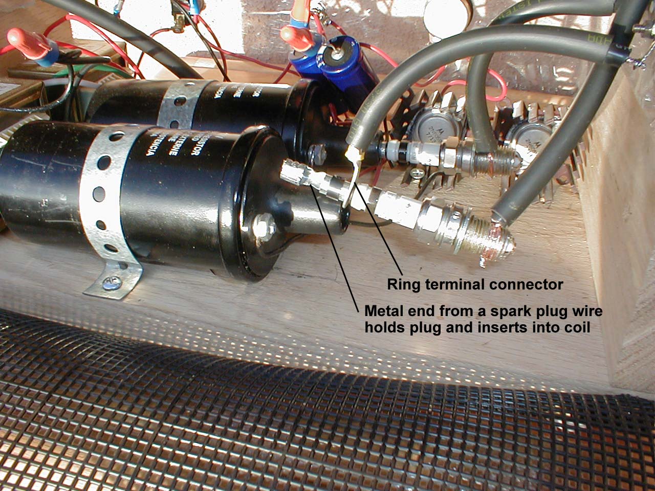
(E) NAPA Coil IC12SB
(F) Bosch Platinum plug 4218. Bend the prong in to provide a gap of .008 or so.
(G) Provides option of "hot-no spark lead". Use ring terminal connector available at Checker Auto Parts KS 12-10 5.5-6 to slip over coil end of plug. Crimp to wire listed under (H). This connector may need to be drilled or reamed out just a little to make it fit the spark plug end but the fit should be tight.
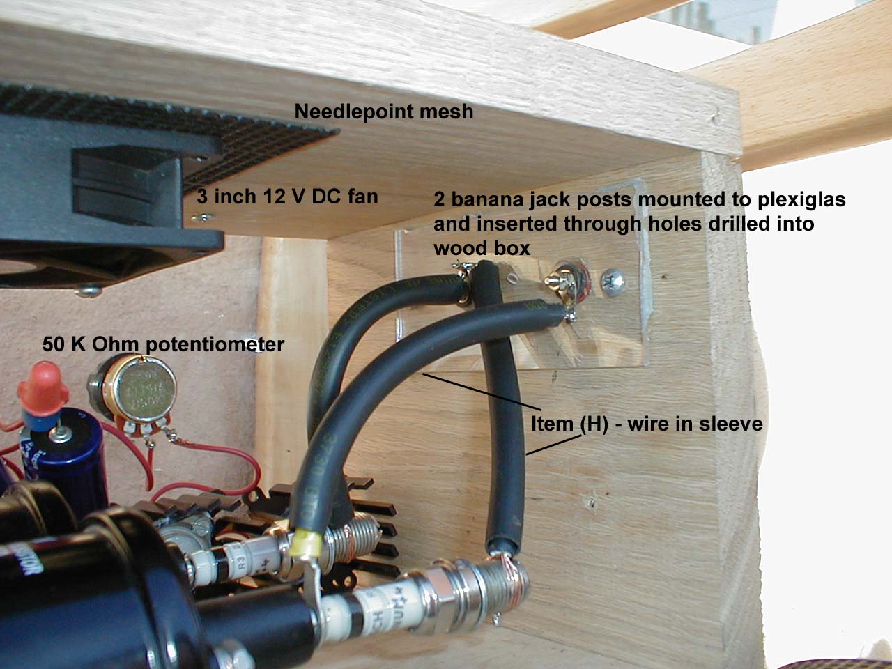
(H) Use heavily insulated copper stranded wire GTO-15 E133573A available at neon shops and 3730 GTO sleeving to slid over wire to increase insulating value. Use same for all high voltage wire (post coils). To secure this wire to the spark plug, strip about 1-1/2 in. insulation off and divide the strands into two. Twist these two groups of strands separately and wrap them around opposite sides of the threaded part of the spark plug. Twist the two strands together tightly on other side and solder. You'll need about 3 ft. of both the wire and sleeve to mount the Phanotron bulb in a stationery position. You'll need about 5-6 ft. more of each if you want to use either the Phanotron or the Violet Ray bulb as a contact device.
(I) BNC jack Radio Shack no. 278-105 to plug in frequency generator. As a frequency source, the programmable F150 is recommended. See http://atelierrobin.tripod.com. You will also need a BNC to BNC cord to connect the F150 to your EMEM3D (Radio Shack part no. 278-964). Those preferring the "traditional" 555 timer circuit may follow instructions at http://www.royalrife.com/emem2.html. In that case, simply wire the output signal of that circuit into this diagram in place of this BNC jack.
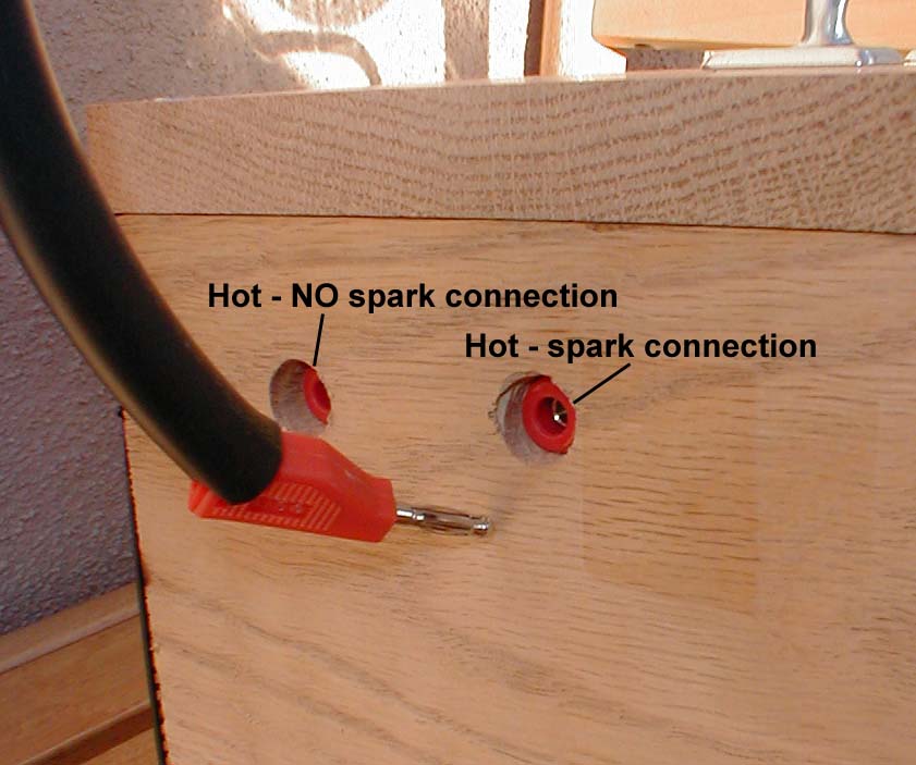
(J) Banana plug post carrying hot-no spark voltage for optional use to light bulb more effectively at frequencies over 10,000 Hz. Connect to one coil, not both. Radio Shack part no. 274-661
(K) Banana plug post ground for plugging in ground end or Phanotron bulb or foot plate. Radio Shack part no. 274-661
(L) Banana plug post carrying hot-spark voltage to Phanotron
or Violet Ray bulb. Connect heavily insulated wires from both
spark
plugs to this post. Radio
Shack part no. 274-661
(M) Phanotron bulb http://www.alley-cats.org/tubebroc.pdf
(N) Violet Ray applicator bulb http://www.baar.com
(O) Grounding pad for feet consists of any conducting metal plate soldered to wire leading to a banana plug to be plugged into the ground post.
(P) Darlington transistor Mouser
part no.511-2N6059
and Heat sink Mouser 532-500403B00
and Transistor mounting socket Mouser
534-4603
and thermal conductive compound Radio
Shack part no. 276-1372. Use the compound between the heat
sink and the transistor.
(Q) Banana plugs Radio Shack part no. 278-321 or something similar.
(R) 50 K Ohm potentiometer Radio Shack part no. 271-1716
(S) Terminal block connector Radio Shack part no. 274-670 to provide a place to connect all the various ground leads.
(T) 3 inch, 12 Volt DC cooling fan. The JDR Microdevices (800-538-5000)
stock number MUFFIN-12V Cooling fan is one choice. Similar fans
are also available at local Radio Shack stores.
Other parts needed available at hardware, auto parts, or general stores.
A couple of colors of 14 guage stranded, insulated wire.
Several crimp-type butt connectors
Solder
Several large wire nuts
6-8 ft. of 3 conductor heavy-duty power cord and a 3 prong plug
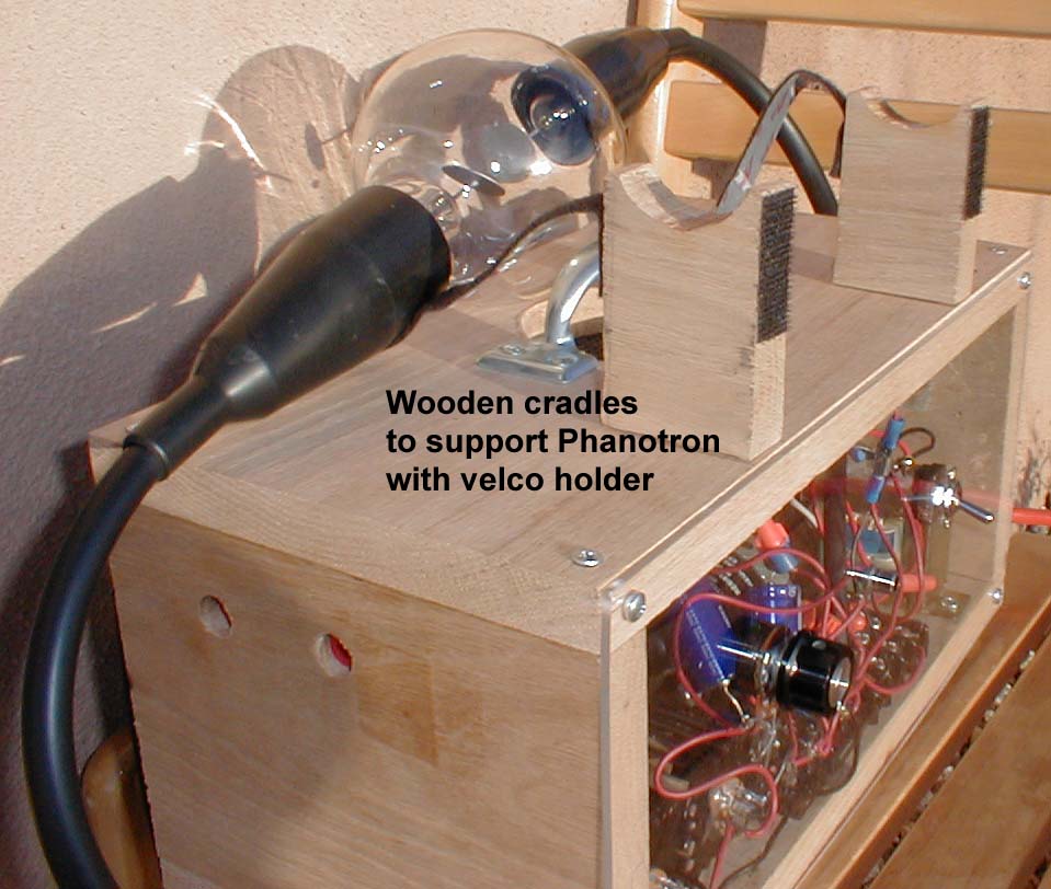
4 ft. length of 1" x 8" board. Cut top and bottom to 14". Sides are 5-1/2".
Metal handle
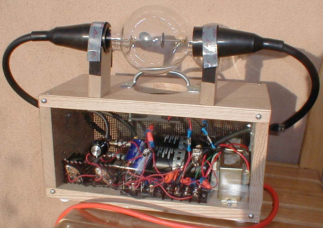
#BU-23 Insulating boots from Mueller Electric for Phanotron bulb ends. They serve to both protect bulb and insulate connections. They may be purchased from Radar Electric, Inc. in Seattle. Phone (206) 282-2511 FAX (206) 282-1598
Hidden inside the rubber insulating boot on the ends of the Phanotron are two one-hole rubber stoppers which fit in the ends of the Phanotron tube allowing the conductor to pass through the hole in the stopper while offering some protection to avoid any stress on the conductor being transferred to the point where it passes into the glass. I bought mine at a hardware store. They could also be found at a chemical or biological supply store, the type of place that sells microscopes, glassware and chemistry sets.
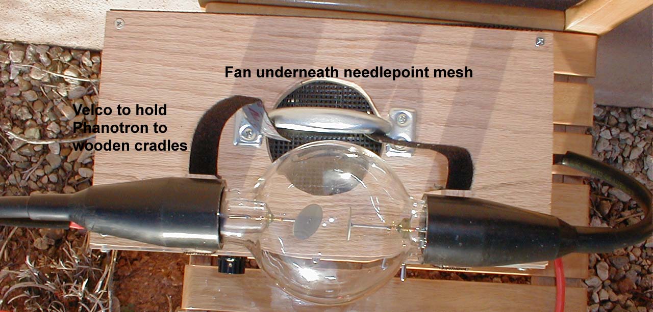
Velcro to attach Phanotron to wooden cradles (general store like Walmart in crafts or sewing section).
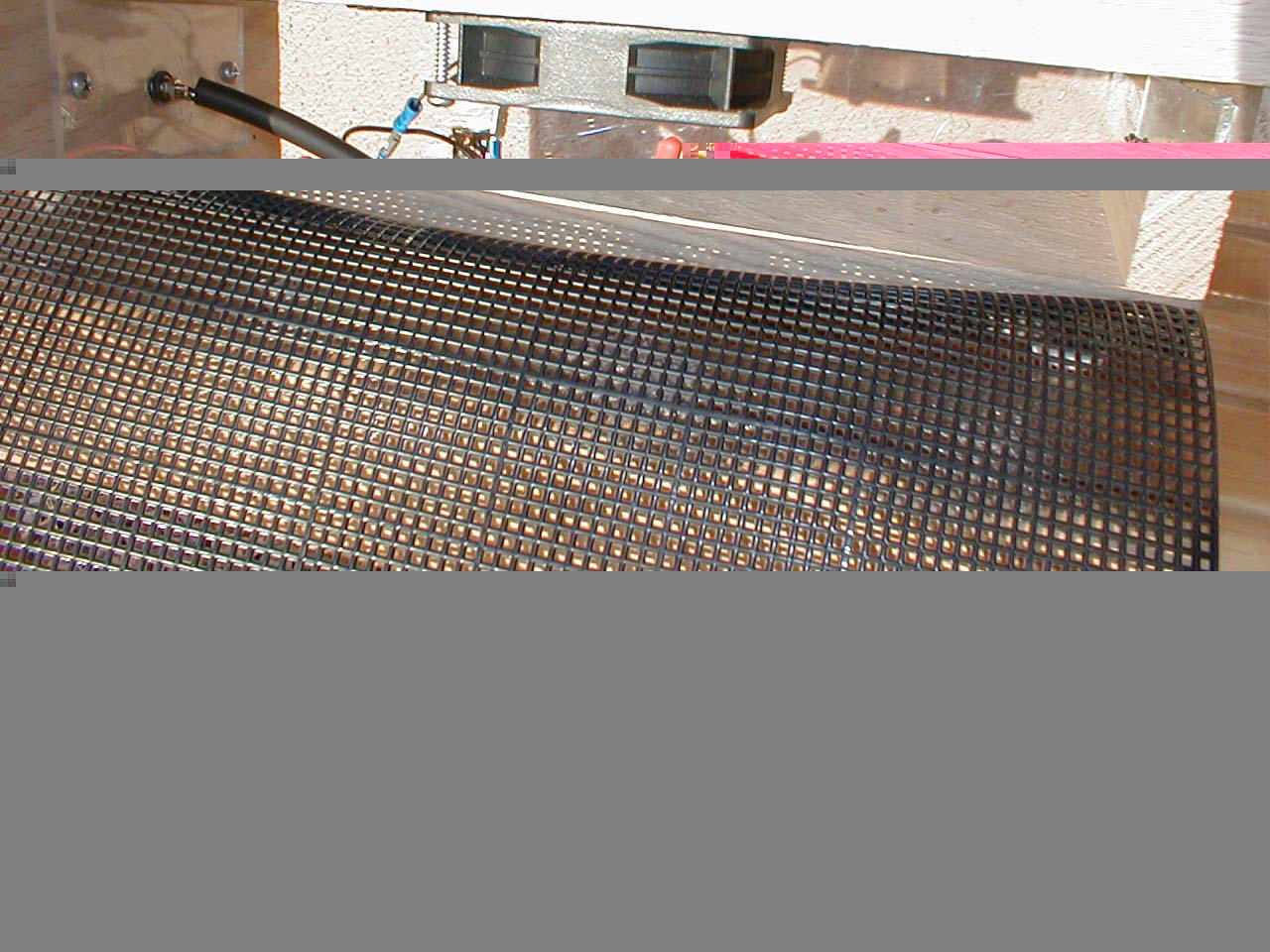
2 sheets - 7 quick count needlepoint mesh for back of instrument and to cover fan hole. (general store like Walmart in crafts or sewing section).
Various size screws
Metal strapping tape with holes to mount coils to wood box floor - hardware store.
2 spark plug wires from an auto parts store. Tear these apart to salvage the metal ends that are designed to connect to the coil. Remove the wire and adapt the other end of the metal piece to fit the spark plug. If properly done, a single piece of this metal will tightly fit over the spark plug and insert into the coil.
Some material to cover front of the instrument and mount the switch and connector to. I found clear plexiglas at the hardware store to be the least expensive and most practical solution. It has the advantage of allowing one to see if the plugs are sparking while in operation. Sheet metal or 1/8 in. wood are other options.